MGL iBox
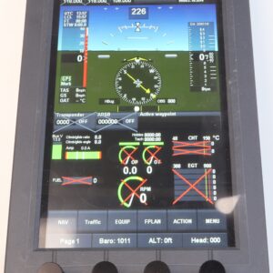
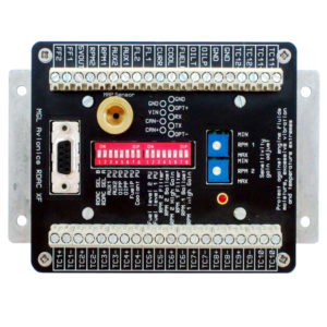
The iBox is the heart of the iEFIS system, and the conductor in the symphony of communication between all system devices and the iEFIS screens. The iBox contains the GPS engine (with antenna connection), the pitot/static sensors and Angle of Attack sensors. The iBox is the hub of communication for all the system devices (AHRS, RDAC, Autopilot Servos) and is also the hub of communication with all third party devices (radios, transponders, ADS-B, VP-X) via its RS-232 and ARINC interfaces.
iBox statusOne iBox is necessary in every iEFIS system, and in cases where maximum redundancy is required, a 2nd iBox can be added to the system. The 2nd iBox acts as a ‘hot standby’ and is ready to take over all iBox tasks automatically when necessary, or on command by the pilot.
Connections
The Power Connector (pigtail harness included with every iBox):
The iBox can be powered by 1 or 2 Power Sources (as in the case of a backup battery system). It also has a Keep Alive Power input that maintains date and time and some non-volatile memory items without using the CR2032 battery, which can result in up to 10 years of life on the CR2032 eliminating the need to change this battery every year. The Outside Air Temp sensor also connects to the Power connector.
The CAN Connector (pigtail harness included with every iBox):
The iBox features 2 CAN buses (CAN 1 and CAN 2). The system devices can be split up in any way on each of the CAN buses.
OAT Probe
Our aluminum OAT probe is included with every iBox
GPS Antenna
Our tuned GPS Antenna is included with every iBox (inside mount)
EFIS LAN coax
An RG-174 EFIS LAN coax cable is included with each system
Gray Code
The Encoder/Misc Connector contains Gray Code (Gillham code) outputs for providing encoded altitude to transponders that don’t have RS-232 inputs.
C4,C2,C2,B4,B2,B1,A4,A2,A1,D4,D2 are provided for this purpose.
Switch Outputs
O1,O2,O3,O4 are switched outputs that can operate external devices based on EFIS scripted controls, for example a Squat Switch for a transponder.
Rotorcraft RPM Inputs
R1 and R2 are auxiliary Rotorcraft RPM inputs
Audio Alarm Output
The AU output is the EFIS audio alarm that provides voice alerts to the intercom/radio system when EFIS alerts are triggered.
Analog and Digital Inputs
These inputs are used to connect remote sensors to the iBox for annunciation on the screen. These include trim and flap position sensors or gear down/up position switches.
A1,A2,A3,A4,A5,A6,A7,A8 are provided this this purpose.
iBox Master/Standby Control
D3 is used to identify a standby iBOX if tied to Ground, or to identify the mast iBox if left open.
Alarm Output
The O5 output switches to Ground on any alarm condition specified in the alarm setup. It thus serves as a swith for a Master Caution alarm lamp or buzzer in the panel.
ARINC Connector
The ARINC bus provides 3 receivers and 1 transmitter for communicating with such devices as the Garmin 430W.
Analog Nav Inputs
The Analog Nav inputs accept CDI/LOC/GS inputs from the +/-150mV differential outputs of older Nav Radios.
RS-232 Connector
The RS-232 Connector Provides 6 RS-232 RX and TX channels for communicating with external devices, such as radios, transponders and ADS-B devices.
- Channels 1 and 2 are high-speed RS-232 and can be used for normal speed RS-232 as well.
- Channels 3, 4 and 5 are normal speed RS-232.
- Channel 6 is reserved for NMEA GPS input/output. This can be used to send GPS position to external devices such as 406 MHz ELT’s. It can also receive NMEA GPS data from external GPSs, such as certified GPS receivers.
Compatible RS-232 Devices
Full Remote Radio Control:
MGL V6 and V10 Com
Frequency Set – External Radio:
SL40 Com, XCOM, Filser, MicroAir, ATR-833
CDI/LOC/GS display from remote NavCom:
SL30 NavCom
ADS-B Control and Weather/Traffic Display:
Navworx ADS-B Tranceiver
Traffic Display:
Zaon XRX, FLARM
Transponder Control and Annunciation:
Sandia STX 165R Remote Mode-C Transponder
Solid-State Circuit Breaker Control and Annunciation:
Vertical Power VP-X or MGL ECB



Reviews
There are no reviews yet.